BAKER SPLINED SHOVEL CLUTCH OVERVIEW
PN 9P400* (CLUTCH ASSEMBLY)
PN 9P401* (CLUTCH ASSEMBLY W/SPLINED 4 SPEED MAINSHAFT)
*- Specify clutch sprocket by adding “-35”, “-36”, “-37” or ”-38” suffix to part number then “-K” for kick only or “-S” for starter ring gear version. Example 9P401-36-S
FEATURES
You know the sad story. The torque on the clutch nut backs off a hair and the key on the transmission mainshaft shears off. This usually happens at the most inconvenient time and place. And the probability of this sad story playing out is greater with performance applications. The splined Shovel clutch kit retrofits and upgrades the stock tapered mainshaft and clutch to a modern 18 tooth spline configuration. Kit includes a fully assembled clutch and splined 4-speed mainshaft to retrofit stock 1970-E84 Big Twins with stock primaries.
The clutch is based off of our 9-plate clutch used on 1990-up applications and fits in the stock primary housing and TTP. We offer 35, 36, 37, and 38 tooth clutch sprockets with our clutches to dial in your overall gear ratio. 18 tooth splined mainshaft installs into the stock 4-speed transmission just like stock.
FITMENT
- 970-E84 Shovelhead® 4 Speeds
- Custom Applications
TOOLS, RESOURCES, REQUIRED PARTS
- Factory Service Manual For Your Motorcycle
- Factory Parts Manual For Your Motorcycle
- Common Hand Tools (allens, sockets, screwdrivers etc.)
- Torque Wrench (ft-lbs. and in-lbs.)
- Dial Calipers or Equivalent (Chain Alignment)
- Straight Edge (Chain Alignment)
- Blue Loctite® (242 Removable) or Equivalent
- Red Loctite® (271 Permanent) or Equivalent
- Modern Style, 18 Tooth Splined Mainshaft Installed; applies only if you did not purchase the complete clutch retrofit kit, pn 9P400*
- 4 Speed Transmission Rebuild Kit (applies only if you purchased the complete clutch retrofit kit pn 9P401*; comes with splined mainshaft pn MS-4- SPLINE.
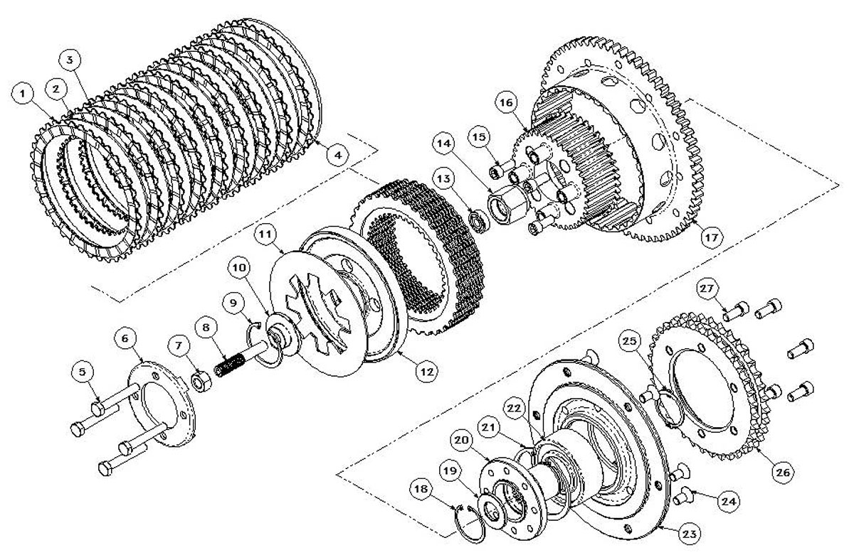
BAKER SHOVEL CLUTCH EXPLODED VIEW
STARTER VERSION SHOWN; FIGURE 1
BAKER SPLINED SHOVEL CLUTCH LEGEND
ITEM | QTY | P/N | DESCRIPTION |
| 1 | 9 | 3223-DSSC | Friction Plate, .095” Thick |
| 2 | 1 | 5579 | Steel Plate, .079” Thick |
| 3 | 7 | 3113-DSSC | Steel Plate, .059” Thick |
| 4 | 1 | 3123-DSSC | Steel Plate, .121” Thick |
| 5 | 4 | 13061 | 5/16-18 X 2.000” Hex Bolts, Grade 8 |
| 6 | 1 | 3073A-DSSC | Clutch Pivot Plate |
| 7 | 1 | 36258 | 7/16-20 Jam Nut |
| 8 | 1 | 37091-4SS | Adjuster Screw |
| 9 | 1 | 1308-175PP | Snap Ring, Keyhole Fitting |
| 10 | 1 | 9P219-56A | Keyhole Fitting |
| 11 | 1 | 3083C-DSSC | Diaphragm Spring, .072” Thick |
| 12 | 1 | 3063B-DSSC | Pressure Plate, Hard Anodized |
| 13 | 1 | .3125 X .875 X .250 | Seal, Adjuster Screw |
| 14 | 1 | 9P215-4SS | Clutch Nut, Left Hand Thread |
| 15 | 4 | 23253 | 5/16-18 X .750” SHCS Black |
| 16 | 1 | 9P234-56 | Inner Hub, Friction Plates |
| 17 | * | 3023-DSSC-4SS | Clutch Basket |
| 17 | * | K3023-DSSC-4S | Clutch Basket |
| 18 | 1 | 1301-150PP | 2” Internal Beveled Snap Ring |
| 19 | 1 | 9P218-56 | Washer, Clutch Seat |
| 20 | 1 | 9P233-56 | Flanged Hub |
| 21 | 1 | 35258 | Snap Ring, Bearing Retainer |
| 22 | 1 | 3207 | Double Row Bearing |
| 23 | 1 | 2020-4SS-R | Clutch Carrier, Raw Finish |
| 24 | 6 | 31F62KFC | 5/16-24 X .625” FHCS Black |
| 25 | 1 | 1460-137PP | Snap Ring, Flanged Hub |
| 26 | * | D40A35HX3.270 | 35 Tooth Chain Sprocket |
| 26 | * | D40A36HX3.270 | 36 Tooth Chain Sprocket |
| 26 | * | D40A37HX3.270 | 37 Tooth Chain Sprocket |
| 26 | * | D40A38HX3.270 | 38 Tooth Chain Sprocket |
| 27 | 6 | 23253 | 5/16-18 X .750” SHCS Black |
* =Customer preference on basket version (kick only or starter ring gear) and chain sprocket tooth count.
NOTE: Mainshaft (pn MS-4-SPLINE) will be included only if you ordered kit part number 9P401* (the legend and exploded view do not show the mainshaft).
CLUTCH PREP / MAINSHAFT INSTALLATION
DISSASSEMBLY:
- Foryour safety, DISCONNECT BOTH BATTERY TERMINALS (FAILURE TO DUE SO COULD RESULT IN PERSONAL INJURY).
- Remove primary drainplug located at the bottom of your primary,drain fluid.
- On some models it is necessary to remove footpegs/floorboards in order to remove the outer primary.
- Remove the outer primary cover.
- Refer to your Factory Service Manual to remove your stock clutch assembly and related primary components using the proper safety precautions and tools.

| IF YOU ARE INSTALLING THIS CLUTCH ASSEMBLY INTO A 4-SPEED TRANSMISSION THAT HAS A TAPERED SHAFT YOU MUST FIRST INSTALL A MODERN 18 TOOTH SPLINED MAINSHAFT (BAKER pn MS-4-SPLINE). |
- If you are installing this clutch assembly in a custom application and the transmission already has a 18 tooth splined mainshaft, skip to page 7 for clutch installation.
- With clutch assembly and primary components out of the way utilizing the Factory Service Manual for proper disassembly. Remove the inner primary assembly and 4 speed transmission.
- With your transmission removed from the motorcycle,disassemble your transmission following your Factory Service Manual.
- Replace the tapered mainshaft with the BAKERTM splined mainshaft provided in the kit (pn 9P401*).

| BAKER DRIVETRIAN DOES NOT SUPPLY THE SNAP RINGS, BEARINGS OR RELATED COMPONENTS FOR THE MAINSHAFT INSTALLATION. PLEASE REFER TO THE FACTORY SERVICE MANUAL AND AFTERMARKET PARTS CATALOG FOR THESE ITEMS. DO NOT REUSE YOUR OLD MAINSHAFT SNAP RINGS OR BEARINGS AFTER DISSASSEMBLY AS THIS MIGHT CAUSE FAILURE TO COMPONENTS, INJURY OR DEATH. |
- Once the splined mainshaft is installed follow your Factory Service Manual for installing the rest of the transmission components, installation of the transmission and installation of the inner primary.

| BAKER HIGHLY RECOMMENDS THAT WHILE REBUILDING YOUR 4 SPEED THAT YOU REPLACE ANY WORN OUT ITEMS OR COMPONENTS THAT YOU MAY FIND DURING THE REASSEMBLY PROCESS. REFER TO YOUR FACTORY SERVICE MANUAL FOR SPECIFICATIONS AND COMPONENT TOLERANCES. |
SPLINED SHOVEL CLUTCH INSTALLATION
BAKER DRIVETRIAN CLUTCH ASSEMBLIES ALL COME READY FOR INSTALLATION. FRICTION PLATES ARE PRESOAKED AT OUR FACILITY AND READY TO RUN, NO DISASSEMBLY REQUIRED.
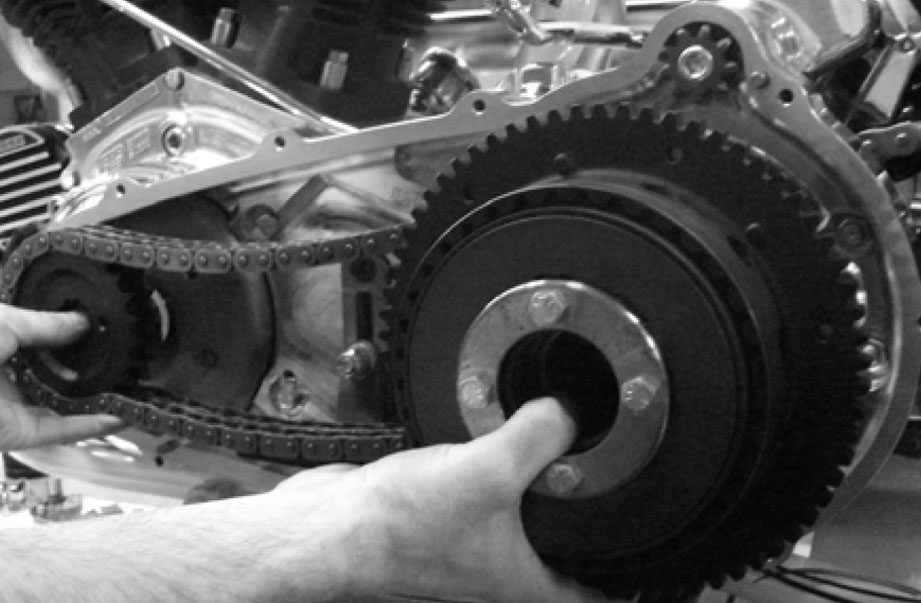
CLUTCH INSTALLATION:- Install your new clutch assembly with primary chain and motor sprocket components following the Factory Service Manual. Figure 2
| INSTALLING THE CLUTCH | FIGURE 2 |

| CHECK THE PRIMARY CHAIN ALIGNMENT TO INSURE CHAIN LIFE AND PREVENT COMPONENT FAILURE. CHAIN ALIGNMENT MUST BE WITHIN .030” (0.76MM) FOR PROPER ALIGNMENT. |
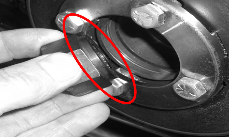
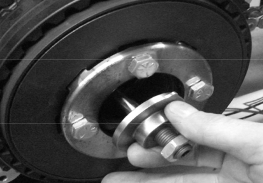
CHAIN ALIGNMENT:- With the clutch, chain and sprocket installed; install the clutch nut (with the machined relief facing toward the clutch; figure 3) and motor sprocket nut; snug at this time.
- Snug the chain adjustment so that the chain is taunt.
- Place a straightedge across the gasket surface.
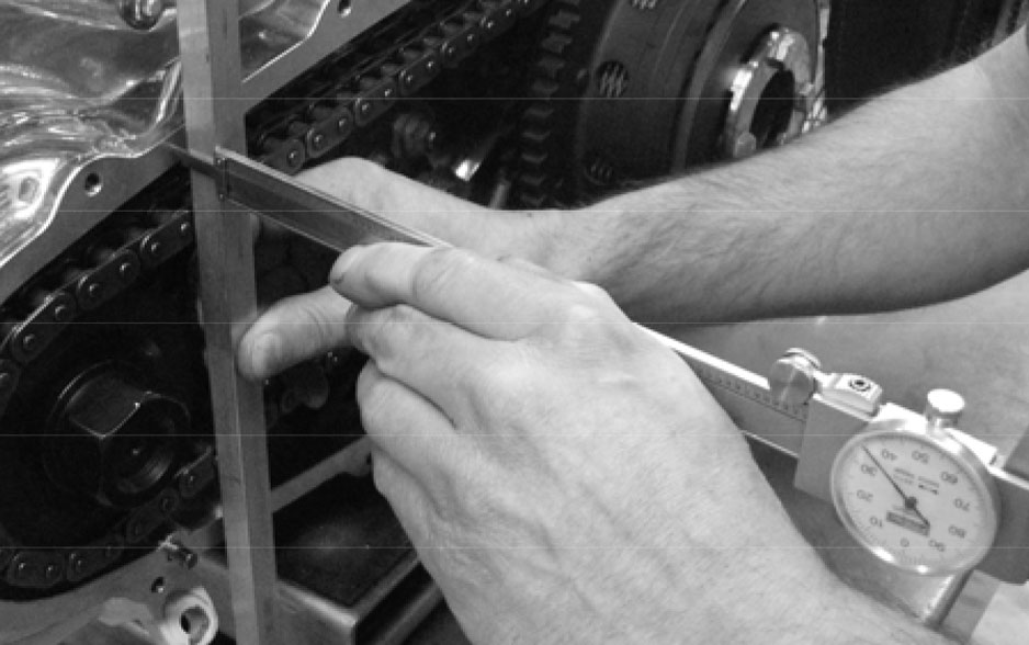
- With a dial caliper, measure the distance from the straightedge to the chain sideplates inside the inner primary. When taking the measurement, measure as close to the motor sprocket as possible. Record this measurement. Figure 4
- Repeat the procedure near the clutch sprocket.
| MACHINED STEP ON NUT | FIGURE 3
CHECKING CHAIN ALIGNMENT | FIGURE 4 |
The two measurements taken will be the spacer thickness needed or subtracted (if required). H-D® offers a wide range of motor sprocket spacers to accommodate your needs.
- If you are within the .030” of chain alignment, loosen your chain, remove the motor sprocket nut and clutch nut.
SPLINED SHOVEL CLUTCH INSTALLATION CONT.- Clean and install the clutch nut as indicated in the chain alignment procedure referencing figure 3 using Red Loctite®.
|

| FOR STOCK APPLICATIONS THE CLUTCH MAINSHAFT NUT COMES SUPPLIED WITH THE ADJUSTER SCREW SEAL INSTALLED TO ENSURE THE STOCK PRIMARY HOLDS VACUUM. IF YOU ARE RUNNING A MODERN PRIMARY THAT NEEDS TO BE VENTED AND IS SEALED OFF FROM YOUR OIL PUMP; REMOVE THE SEAL (PN .3125 X .875 X .250) FROM THE CLUTCH NUT. USE FIGURE 1 FOR REFERENCE. |
- Clean and install motor sprocket nut using Red Loctite®
- Torque to Factory specifications following your Factory Service Manual.
- Adjust primary chain following steps listed in your Factory Service Manual.
- Install clutch adjuster Key Hole Fitting and snap ring provided. Figure 5
| INSTALLING KEYHOLE FITTING | FIGURE 5 |

| ALWAYS WEAR PROPER EYE PROTECTION WHEN REMOVING AND INSTALLING SNAP RINGS. SLIPPAGE MAY PROPEL THE SNAP RING INTO THE AIR. |
- Adjust the clutch following steps listed in your Factory Service Manual.
- Install outer primary and fill primary with proper fluid / amount through the derby cover opening (clutch inspection opening). Fluid recommendation and level found in your Factory Service Manual.
- Install derby cover(clutch inspection cover)with new gasket. Torque to Factory Service Manual specifications.
- If floor boards or pegs were removed to install your clutch reinstall them as time per Factory Service Manual.
TO PROLONG THE LIFE OF YOUR NEW BAKER SPLINED SHOVEL CLUTCH ALWAYS RE-ADJUST THE CLUTCH AFTER THE INITIAL “BREAK IN” PERIOD. THIS CAN VERY DEPENDING ON YOUR RIDING STYLE; BETWEEN 500-3000 MILES. |

