Baker Drivetrain Compensator Sprocket for Twin Cam & M8 Models Installation Instructions

Baker Drivetrain Compensator Sprocket Kit
FEATURES
The BAKER 730-67 & 730-M8 Compensator Kit features improved function, quieter operation, and extended durability over the stock Factory configuration. These improvements were achieved by increased cam lobe geometry width and ramp angles (figure 1) with adding a circular oil skirt (figure 2) that channels primary lubricant into the cam lobe region.
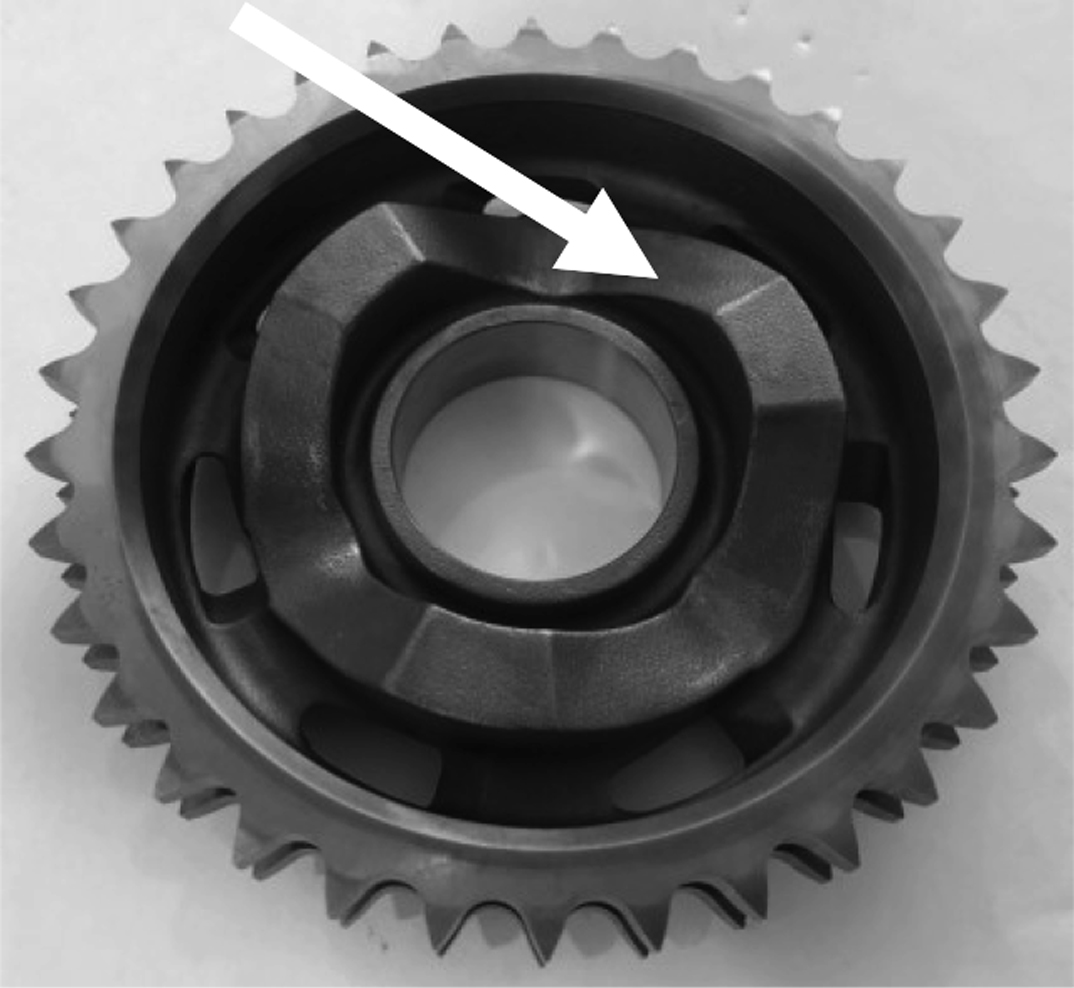
Figure 1, Cam Lobes
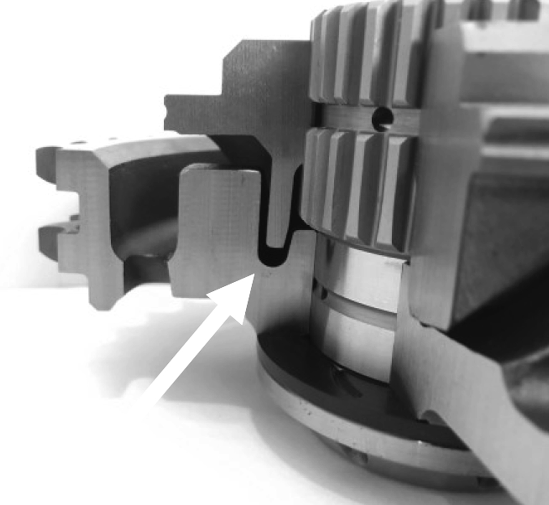
Figure 2, Oil Skirt
FITMENT
- 2006 – 2016 Dyna Models
- 2007 – 2017 Softail | Touring Models
- 2017 – Later Touring Milwaukee 8 Models
- 2018 – Later Softail Milwaukee 8 Models
Compensating Sprocket currently does not fit Softails with wide rear tires (IE: 240 Rear tire Fat Boy® & Breakout®)
PARTS, SPECIAL TOOLS, and REFERENCE MATERIALS REQUIRED
To complete the installation of the BAKER Compensator Kit the following is required:
- A new primary cover gasket.
- T-70 Torx socket, removal and installation of sprocket assembly.
- 9/16-12 bottoming tap or thread chaser to clean the sprocket shaft female threads.
- Early Factory compensators utilized a rotor with an integral compensator spring cup. Bikes equipped with this early style rotor must be retrofitted with a PN 30041-08A late style rotor.
- 2006 Dyna must also retrofit the stator with PN 30017-07.
- 32fl.-oz bottle of Primary lubricant; see details on Page 5.
- Primary Drive locking tool HD-48219 (Touring models) HD-47977 (Softail/Dyna)
- These instructions make references to the Factory service manual. A service manual for your year and model motorcycle is required.
HIGHLY RECOMMENDED ADDITIONAL PART
With the primary drive disassembled to install the new compensator, BAKER highly recommends that the automatic chain tensioner be replaced with a 177-67K Attitude Adjuster (figure 3). Extensive testing and durability miles have proven that the 177-67K Adjuster puts less bending moment loading on the motor sprocket shaft and the transmission mainshaft thereby extending the life of the drivetrain components.
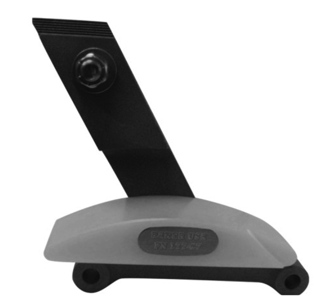
Figure 3, BAKER Attitude Adjuster
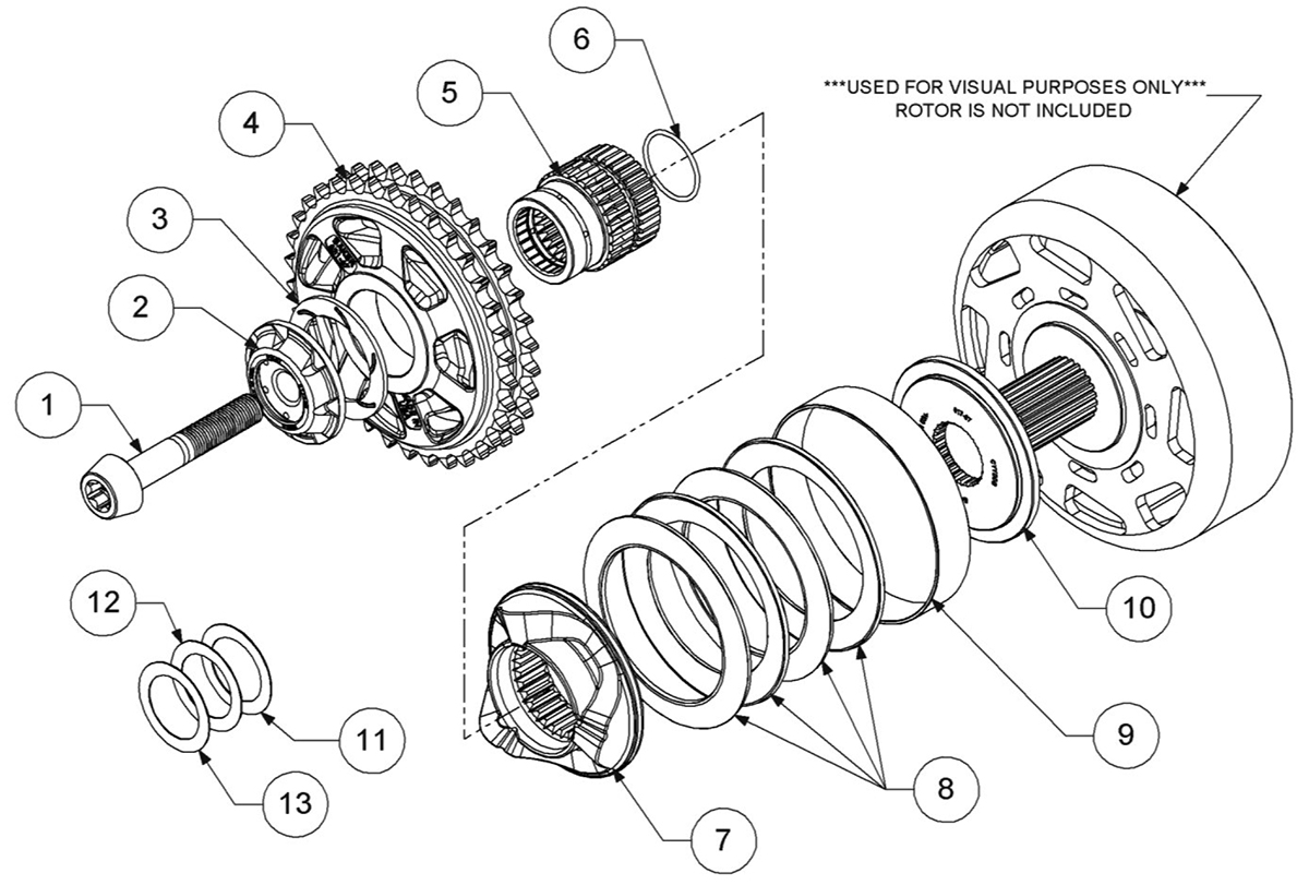
Figure 4, Detailed View
ITEM | Qty | p/n | description |
| 1 | 1 | 10500031 | 9/16-12, Bolt |
| 2 | 1 | 619-67 | Retainer, Comp Sprocket |
| 3 | 1 | BD-401064 | Thrust Washer |
| 4 | 1 | 621-67F | 34 Tooth Comp Sprocket |
| 5 | 1 | 622-67F | Motor Extension Shaft |
| 6 | 1 | 9262K682 | O-Ring, 2mm x 31mm Buna |
| 7 | 1 | 623-67-4 | Cam Slider |
| 8 | 4 | 620-67B | Belleville Spring |
| 9 | 1 | 624-67-4 | Retainer, Spring |
| 10 | *1* | 617-67 | Spacer, Spring Pack |
| 11 | 1 | 3088A438 | Shim, 1-1/4 x 1-3/4 x .030” |
| 12 | 1 | 3088A388 | Shim, 1-1/4 x 1-3/4 x .020” |
| 13 | 1 | 3088A328 | Shim, 1-1/4 x 1-3/4 x .010” |
** PN617-67 IS NOT SUPPLIED WITH MILLWAUKEE-EIGHT® SPROCKET KITS; PN 730-M8**
REMOVAL
Remove the outer primary and existing compensator sprocket per the Factory service manual but add the following steps to the job:
- We highly recommend that the stock 9/16-12 compensator bolt be heated with MAP gas, prior to removal, to soften the red Loctite®. Without the use of heat, the hardened red Loctite® may break up into pieces and act like a very coarse abrasive and destroy the bolt threads as shown in figure 5.
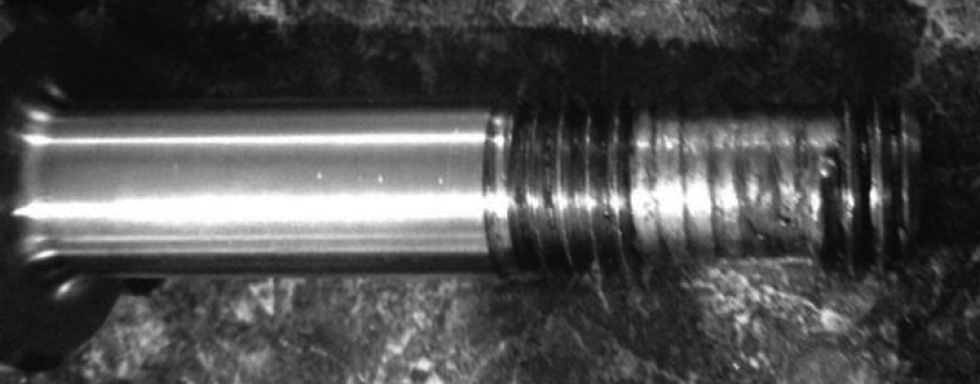
Figure 5, Destroyed Bolt Threads
- After the stock compensator bolt is removed, clean out the 9/16-12 female sprocket shaft threads with a 9/16-12 bottoming tap or thread chaser.
- Thoroughly purge the 9/16-12 threads with lacquer thinner or brake clean and blow all debris out of the blind hole with shop air.
| REMEMBER SAFETY FIRST; WEAR EYE PROTECTION WHEN USING SHOP AIR |
INSTALLATION
The 730-67 & 730-M8 installs and replaces the stock factory compensator components with no modifications required.
- Apply some primary lubricant to the compensator sprocket bore, cam lobes, cam slider cam lobes, motor extension shaft splines (inner/outer) and pre-installed motor extension shaft O-Ring prior to installation, figure 6.
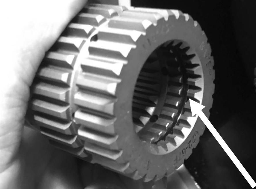
Figure 6, Oil O-Ring Inside Extension Shaft
- The compensator sprocket installs in the same sequence as shipped and as shown in figure 4 (detailed view).
- For non-Milwaukee-Eight® models, install the spacer (617-67) onto the crankshaft.
- Milwaukee-Eight® models will not use a spacer as the spring cup will go against the stator rotor.
- Install the cam slider (623-67-4) onto the motor extension shaft (622-67F) and slide the spring cup assembly (624-67-4 w/620-67B, 4pcs) onto the back of the cam slider, figure 7.
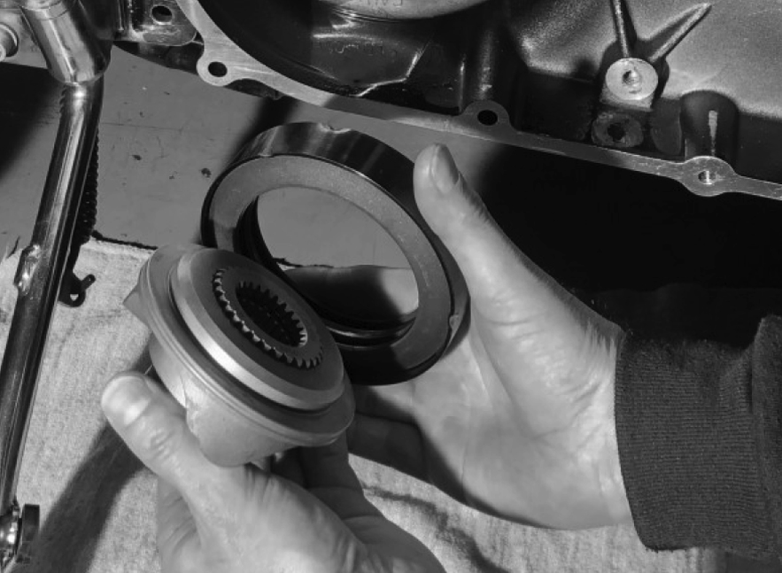
Figure 7, Cam Slider Assembly
- Align the crankshaft splines and extensions shaft splines and slide the assembly onto the motor crankshaft, figure 8.
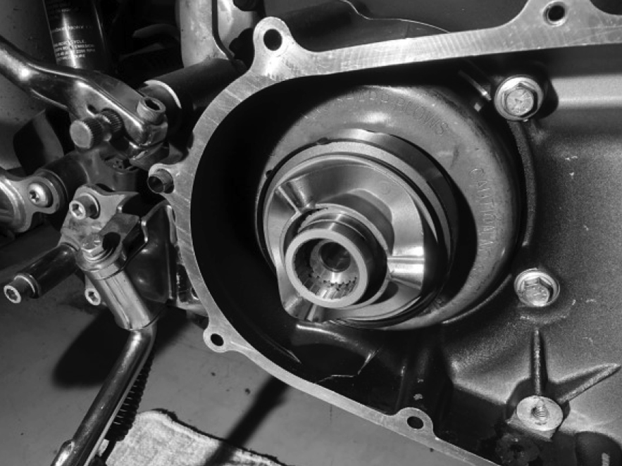
Figure 8, Slider Assembly Installed on Crankshaft
- Install the compensating sprocket (621-67F), retainer (619-67) with thrust washer (BD-401064) and bolt (10500031).
| CHECK THE PRIMARY CHAIN ALIGNMENT TO ENSURE CHAIN LIFE AND PREVENT COMPONENT FAILURE. CHAIN ALIGNMENT MUST BE WITHIN .030” (0.76MM) FOR PROPER ALIGNMENT. |
CHAIN ALIGNMENT:
- Install just the clutch and BAKER Compensator Sprocket; NO CHAIN. Install the clutch nut and bolt (10500031); snug at this time.
- Use some spacers to replicate the thickness of the outer primary and install the long ¼-20 threaded bolt into the primary as shown in figure 9 and torque down per your factory service manual.
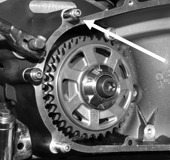
Figure 9, Spacers Shown on Long Bolts
- Place a straightedge across the end of the sprockets. With a dial caliper, measure the distance from the straightedge to the gasket surface of the inner primary. When taking the measurement, measure on the front area of the primary for the compensator and rear area for the clutch. Record this measurement. Figure 10 & 11.

Figure 10, Checking Comp Sprocket
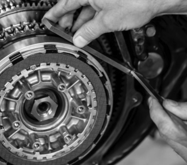
Figure 11, Checking Clutch Sprocket
- Compare the two measurements taken.
The two measurements taken (the difference) will be the spacer thickness needed (if required). Motor sprocket shims are supplied (3088A438, 3088A388, and 3088A328) to accommodate your needs.
If shims are required, install the shim on the crankshaft up against the stator rotor assembly before the compensator sprocket kit is installed.
When the two measurements are within .030” you may proceed to final assembly. - Install the primary chain, clean and apply some red Loctite® to the compensator bolt (10500031) and clutch nut threads. Using a primary locking tool between the sprockets, torque the clutch nut to factory specifications following your service manual. Torque the compensator bolt (10500031) to 100ft-lbs, then back off (loosen) a half turn then re- torque to 175ft-lbs for final torque. A properly installed BAKER Compensator Sprocket looks like that shown in Figure 12.

Figure12, Installed BAKER Compensator Sprocket
PRIMARY CHAINCASE LUBRICANT
Fill the primary per the Factory Service Manual.
BAKER recommends that Spectro Heavy Duty Primary Chaincase Oil or HD Formula+ Transmission and Chaincase Lubricant (99851-05) be used.


