Baker Drivetrain Direct Drive 6-Speed Installation Instructions

Baker DD6 Installation Instructions
Overview
Features
The BAKER DD6 Transmission Builder’s Kit comes with all of the necessary components to convert your stock 5-Speed into a 6-Speed, providing smoother shifting, positive neutral-finding, and reduced cruising RPM on the highway. With proven technology and helical 4th, 5th, and 6th gears, your highway cruising is noise-free.
Application And Required Hardware
A Builder’s Kit is, as the name implies, for building a BAKER DD6 transmission using an existing case housing and its peripheral hardware. The following 5-speed components are required to complete this installation:
- Transmission case
- Pawl and sprocket spacer seals
- Top cover and fasteners
- Clutch release cover & fasteners
- Clutch release mechanism and push rod hardware
Included Parts
Parts Provide With The Baker DD6 Builders Kit
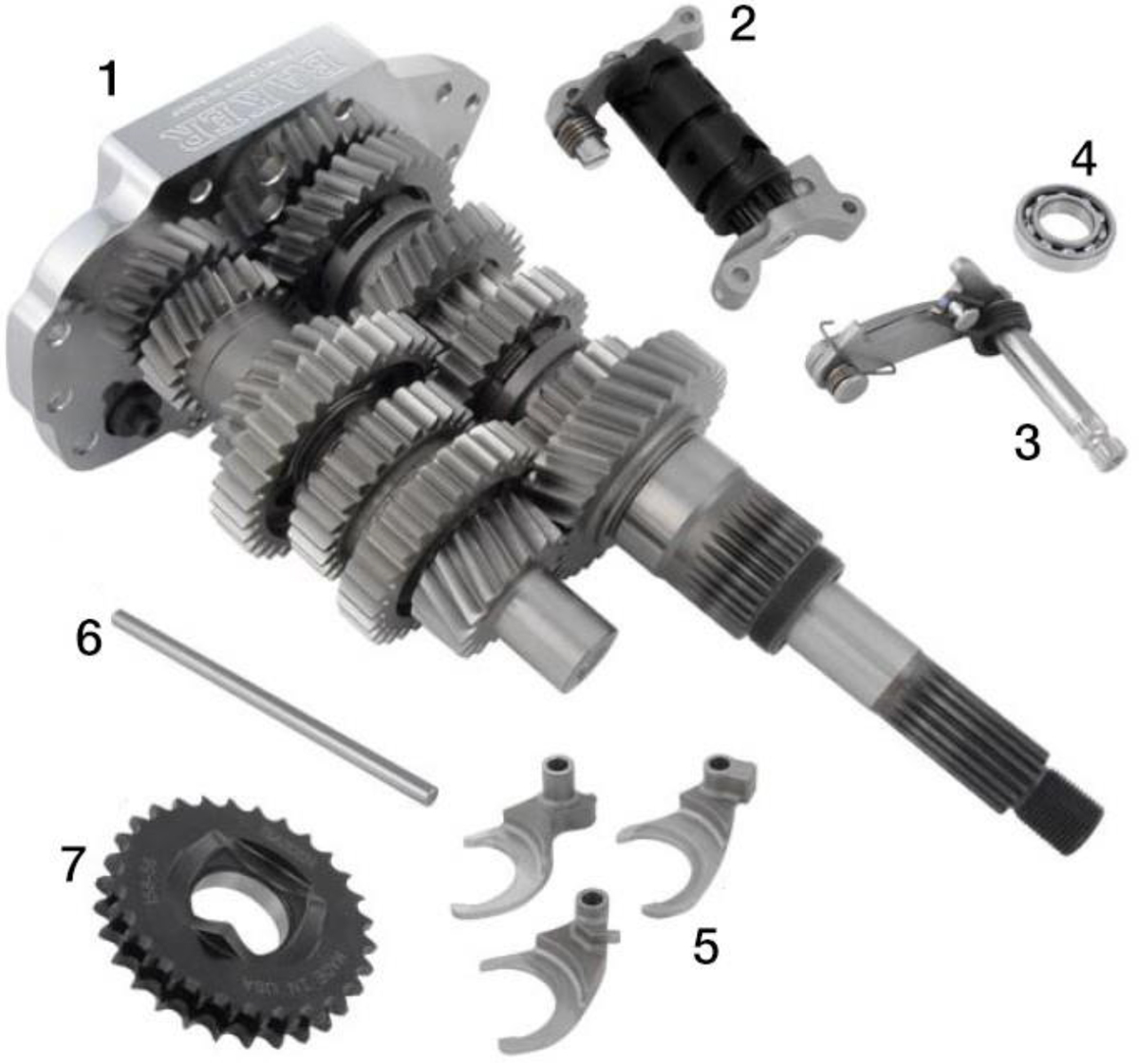
The Following Parts Are Included As Shown In Figure 1
- Assembled DD6 gear set on BAKER bearing door.
- Shift drum with redundant neutral pillow blocks.
- Shifter pawl, model specific.
- New P/N: 6209 main bearing and beveled snap ring.
- Three shift forks, labeled #2, #3, and #4.
- Bearing grade fork rod.
- 28T Compensating sprocket and chain, model specific.
Baker DD6 Builder Kit Included Parts Detail
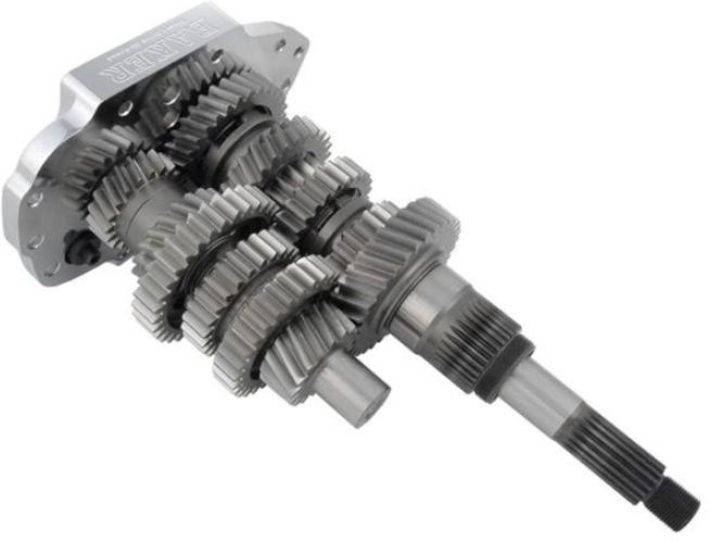 | DD6 GEARSET P\N: DD411 (3.24 1ST) OR DD401 (2.94 1ST) |
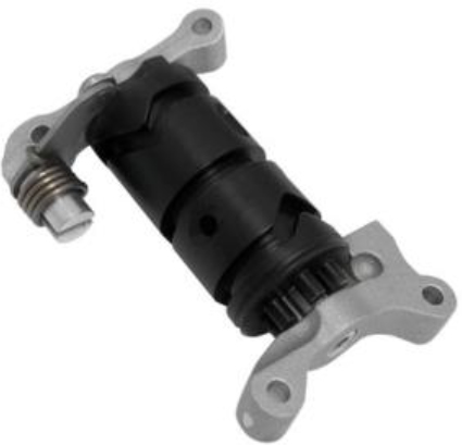 | SHIFT DRUM P\N: 124E-DD6-A |
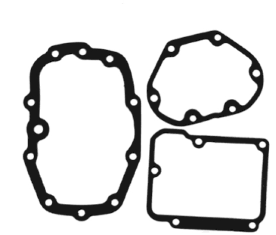 | GASKET SET P\N’S: 36801-87B (SIDE COVER) 35652-79B (TRAP DOOR COVER) 34904-86E (TOP COVER) |
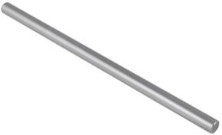 | FORK ROD P\N: 122-6 |
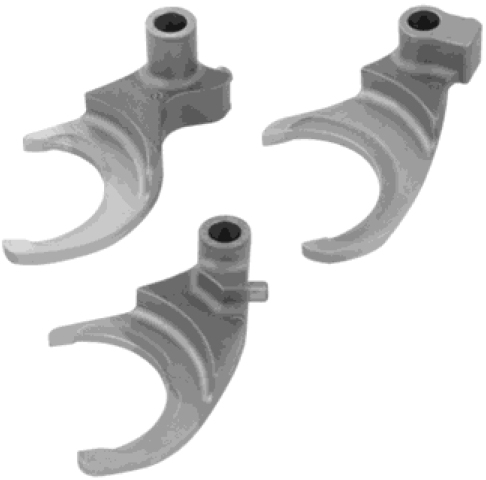 | SHIFT FORKS P\N’S: 172-DD6 173B-DD6 174-DD6 |
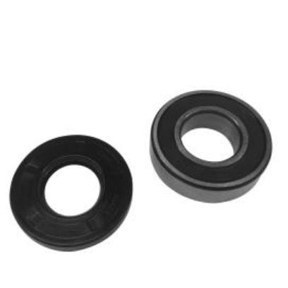 | HIGH TORQUE BEARING W/SEAL P\N: P205PP-H (BEARING) P\N 25X52X07ADL (SEAL) |
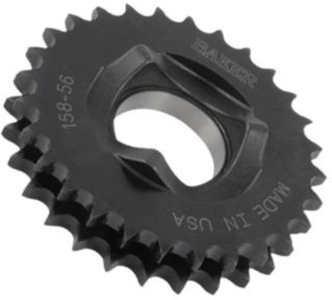 | SPROCKET P\N: 158-56 |
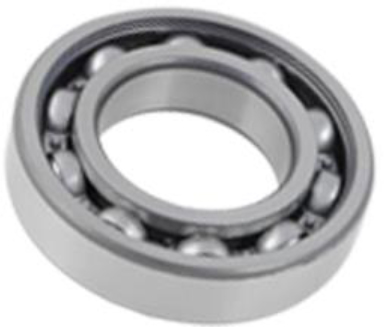 | MAIN BEARING P\N: 6209 |
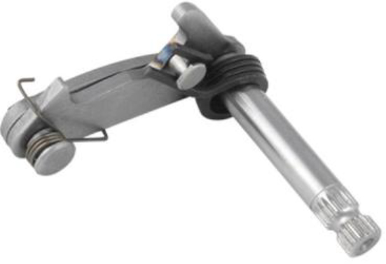 | SHIFTER PAWL P\N: 555-56C-A OR 555-56LD-A |
Exploded View Diagrams
Shift System, View 1
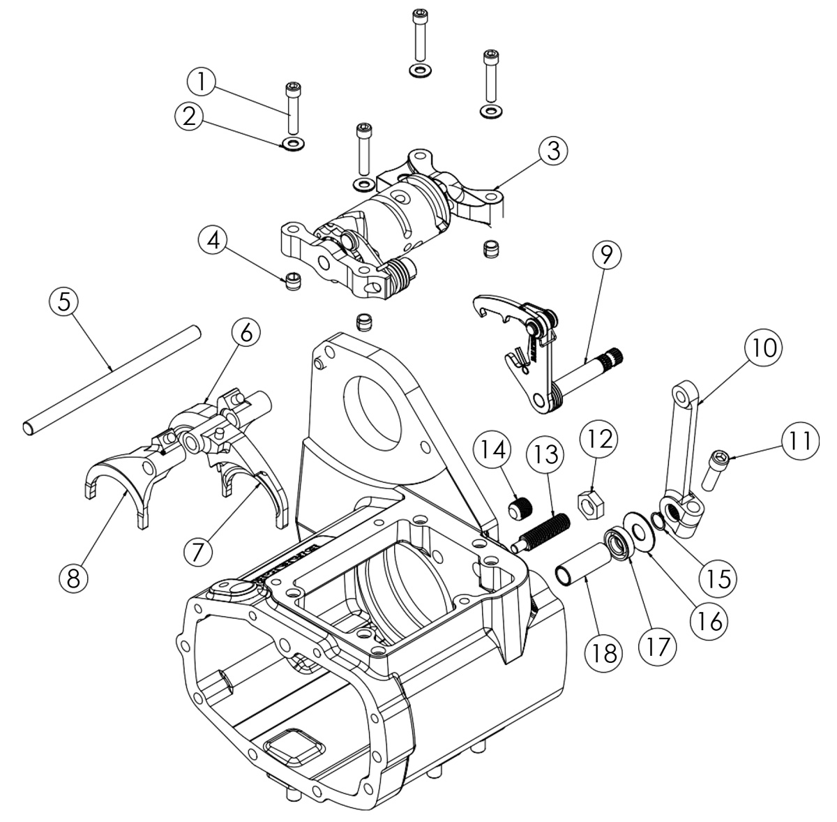
Number | Part Number | DESCRIPTION | QTY |
| 1 | 23207 | 1/4-20 x 1 1/4 SHCS Bolt | 4 |
| 2 | 33001 | 3/16 Washer | 4 |
| 3 | 124E-DD6-A | Shift System | 1 |
| 4 | 609B | Alignment Pin, 5/16 x 3/8 | 4 |
| 5 | 122-6 | Fork Rod | 1 |
| 6 | 172-DD6 | Fork, 2nd MS | 1 |
| 7 | 173B-DD6 | Fork, 3rd CS | 1 |
| 8 | 174-DD6 | Fork, 4-5 MS | 1 |
| 9 | 555-56C-A | Shifter Paw | 1 |
| 10 | 33715-85SA | Shift Lever, Stainless | 1 |
| 11 | 31F100KCSS/P | 5/16-24 x 1 SHCS, Polished | 1 |
| 12 | 70813 | 7/16-14 Jam Nut, Stainless | 1 |
| 13 | 152-56B | Eccentric Adjuster | 1 |
| 14 | 25702 | 1/2-20 x 1/2 Set Screw | 1 |
| 15 | 68010 | 7/16 Snap Ring, External | 1 |
| 16 | 6497HW | Washer, Shifter Pawl | 1 |
| 17 | 12045 | Seal, Shifter Pawl | 1 |
| 18 | 33114-79 | Bushing, Shifter Pawl | 1 |
Gearset, View 2

| Number | Part Number | DESCRIPTION | QTY |
| 1 | 12035B | Oil Seal, Main Drive Gear | 1 |
| 2 | HK2520 | Bearing, Main Drive Gear | 2 |
| 3 | DD6-6M-1 | Main Drive Gear, 6th Main | 1 |
| 4 | DD6-2M-1 | Gear, 2nd Main | 1 |
| 5 | 11067 | Retaining Ring | 5 |
| 6 | 6003B | Thrust Washer | 5 |
| 7 | DD6-3M-1 | Gear, 3rd Main | 1 |
| 8 | 8876A | Bearing, Split Cage | 5 |
| 9 | DD6-4M-1 | Gear, 2nd Main | 1 |
| 10 | DD6-4C5-1 | Dog Clutch, 4th - 5th Gear | 1 |
| 11 | DD6-5M-1 | Gear, 5th Main | 1 |
| 12 | TWD1423 | Thrust Washer | 2 |
| 13 | DD6-MS | Mainshaft w/ 1st Gear (3.24 Standard) | 1 |
| 13A | DD6-MS-2.94 | Mainshaft w/ 1st Gear (2.94 Optional) | 1 |
| 14 | DD6-CS | Countershaft (3.24 Standard 1st) | 1 |
| 14A | DD6-CS-2.94 | Countershaft (2.94 Optional 1st ) | 1 |
| 15 | BK2526 | Countershaft Bearing (not shown) | 1 |

The Following Parts Are Included As Shown In Transmission Housing View 3
Number | Part Number | DESCRIPTION | QTY |
| 1 | 25C225KCSS/P | 1/4-20 x 2 1/4” SHCS, Polished SS | 1 |
| 2 | 25C125KCSS/P | 1/4-20 x 1 1/4” SHCS, Polished SS | 6 |
| 3 | 6099SS | 1/4” Washer, Stainless | 13 |
| 4 | 33902-98 | Switch, Neutral Indicator | 1 |
| 5 | 34468-56A | Top Cover, LSD 91-98 ST | 1 |
| 6 | 34904-86E | Gasket, Top Cover | 1 |
| 7 | 609B | Alignment Dowel | 4 |
| 8 | 214C-56CB | BAKER Transmission Housing | 1 |
| 9 | 26770 | Dowel, Starter | 1 |
| 10 | 37089-84 | Actuator Rod | 1 |
| 11 | TWC411 | Thrust Washer, Actuator Rod | 2 |
| 12 | TC411 | Bearing, Actuator Rod | 1 |
| 13 | 37088-90 | Clutch Rod | 1 |
| 14 | 10705-01149 | C-Clip, Actuator Rod | 1 |
| 15 | 66853 | O-ring | 2 |
| 16 | 124-5L38 | Piston, 1.375” Bore | 1 |
| 17 | 459-6 | Clutch Cover, Hydraulic, Indian, Chrome | 1 |
| 18 | 45-9404 | Bleeder Valve | 1 |
| 19 | 25C225KCSS/P | 1/4-20 x 2 1/4” SHCS, Polished SS | 2 |
| 20 | 25C125KCSS/P | 1/4-20 x 1 1/4” SHCS, Polished SS | 4 |
| 21 | 130-56BSP | Dipstick | 1 |
| 22 | 66825 | O-ring, dipstick | 1 |
| 23 | 1302-334PP | 3 11/32” Snap Ring, Internal, Beveled | 1 |
| 24 | 36801-87B | Gasket, Side Cover | 1 |
| 25 | 24050 | 1/4-20 x 5/8” BHCS, Bearing Retainer Plate | 1 |
| 26 | 7340BD | 3/4-16 Jam Nut | 2 |
| 27 | 6304 | Bearing, Trap Door | 2 |
| 28 | 6100 | 5/16” Washer, Stainless | 4 |
| 29 | 31C125KCSS/P | 5/16-18 x 1 1/4” SHCS, Polished SS | 4 |
| 30 | 133-DD6 | Bearing Retaining Plate | 1 |
| 31 | 23202 | 1/4-20 x 5/8” SHCS, Bearing Retainer Plate | 5 |
| 32 | 51740-001 | 3/8-24 Drain Plug | 1 |
| 33 | 132A-DD6 | Bearing Door, w/ Ear | 1 |
| 34 | 35652-79B | Gasket, Bearing Retainer | 1 |
| 35 | F1409 | Door Magnet | 1 |
| 36 | 23205 | 1/4-20 x 1” SHCS | 1 |
| 37 | 11733A | Stud, Rigid transmission | 5 |
| 38 | BK2526 | Bearing, Countershaft Case | 1 |
| 39 | 12067B | Seal, Main Drive Gear | 1 |
| 40 | 33344-94S | Pulley Spacer | 1 |
| 41 | 11165A | Quad seal | 1 |
| 42 | 6209 | Bearing, Main Drive Gear | 1 |
Skill Knowledge & Tools
Required Reading
Regardless of the skill level or experience of the installer of the Builder’s Kit, it is highly recommended that a genuine H-D Motor Company® parts catalog and Factory Service Manual be available for reference on the installation. The installation instructions for the BAKER DD6 will make reference to the Factory Service Manual. Any Factory manual from 1990 to present will be sufficient.
Special Tools
The only special tools required are the same tools that would be required for any 5-speed installation. For a list of other required tools, please consult your Factory Service Manual.
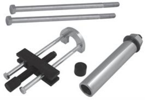
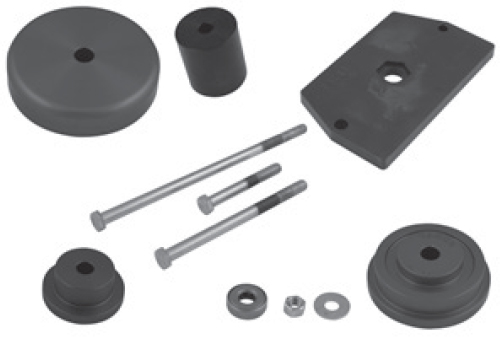 TOOL A-56 | For removing and installing of the main drive gear and main drive bearing, BAKER DRIVETRAIN part number TOOLA-56 is required; an equivalent tool is also available from your local Harley® dealer, part number 35316A. |
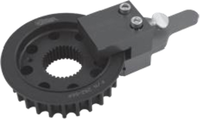
 TOOL B-56 | For removing and installing the bearing inner race on the transmission mainshaft, BAKER DRIVETRAIN part number TOOLB-56 is necessary. Harley® also offers an equivalent tool, 34902A. |
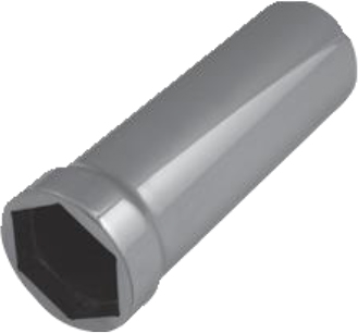
 TOOL C-56 | For removing and installing the 1-7/8 transmission pulley nut, BAKER DRIVETRAIN part number TOOLC-56 and TOOLD-56 will be needed. The Harley® part number is 94660-37A. |
 TOOL D-56 |
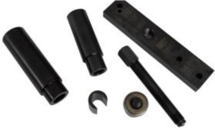 JIMS USA TOOL | It is recommended that the Countershaft Bearing is replaced at the time of installation, using an approved tool and procedure, such as the Jims Countershaft Cup Bearing Tool. JIMS USA PN#739. |
Baker DD6 Builers Kit Assembly
Case Preperation / Gearset Removal
If the Builder’s Kit is replacing an existing 5-speed, refer to your FactoryService Manual section 7, Mainshaft/ Countershaft removal. Follow gearset removal procedure.
Next, refer to section 7, Main Drive Gear removal, and follow removal procedure. Be sure to clean the case with Brake Cleaner or another suitable cleaner before continuing with installation.
If the Builder’s Kit is going into a new case, no preparation is needed.
Case Clearance Checks
The BAKER DD6 hardware is designed to fit in stock H-D® transmission cases without modification to the case or the six-speed components. Since most aftermarket cases are styled after the H-D® equivalent, the hardware will fit into aftermarket cases as well. This applies in most situations, but there are exceptions. The internal walls of the cases ‘float around’ occasionally in H-D® and aftermarket castings, this is not an indication of poor quality, but rather, is inherent of the casting process. Be sure to check for any potential interference before final installation of the gearset. Any necessary case modification can be done with a die-grinder.
Gearset Installation
Special note: 2000 - 06 88B Softail transmissions have a noted shortcoming with the landing that supports the P/N: 6209 bearing. This landing comes from the factory with a very thin wall thickness and cracks in the corner between the landing and the P/N: 6209 bearing bore. Inspect carefully for this situation. | 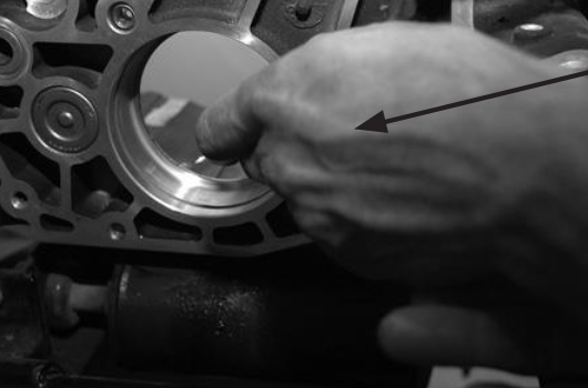 Inspect This Landing | FIGURE 1 |
1. Install the new main drive gear bearing provided, O.E. P/N: 6209, NEVER install the bearing into the case by applying pressure to the inner race of the bearing - you will destroy the bearing and it may fail. Install the new retaining ring with the bevel facing out. | 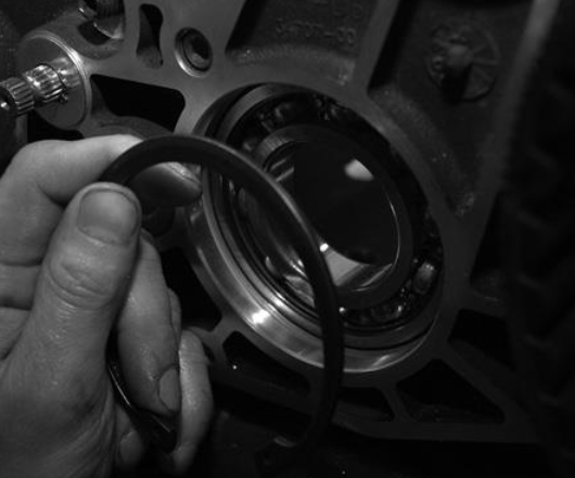 Step 1: Install The New Bearing | FIGURE 2 |
2. Remove the main drive gear from the BAKER DD6 gearset/trap door assembly by simply sliding it off the mainshaft. To install the main drive gear into the transmission case use BAKER DRIVETRAIN part number TOOLA-56 and follow the directions as described in the Factory Service Manual. | 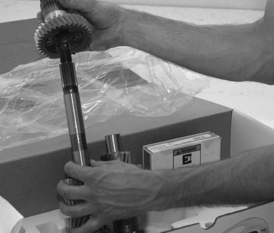 Step 2: Removing The Main Drive Gear | FIGURE 3 |
All models require the changing of the eccentric adjustment screw for proper shift pawl adjustment. 2000-06 Softails and all ‘01 - ‘06 FLT and ‘05 Dyna models will require this change. The adjustment screw and locking nut are provided in the Builder’s Kit.
3. At this time it is necessary to install the provided shifter pawl. The pawl included with the Builder’s Kit is essential to the proper operation of the shift mechanism. It was specifically designed to improve fork shifting and operate in conjunction with the new shift drum to provide ease and smoothness of shifting. | 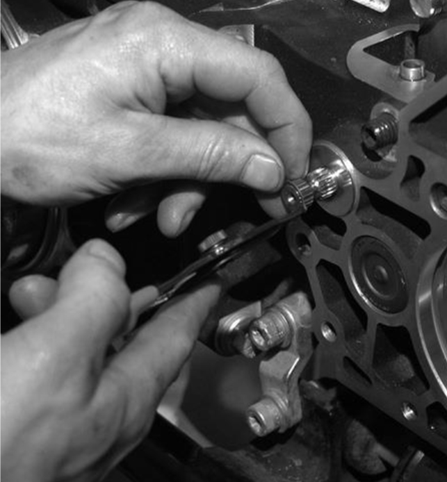 Step 3: Installing The Shifter Pawel And Snap Ring | FIGURE 4 |
It will be necessary to replace the 7/16” external snap ring and washer that retains the pawl with the ones provided at this time.
4. Hang the door gasket provided onto the case dowel pins and carefully push it down to seat it against the gasket surface. | 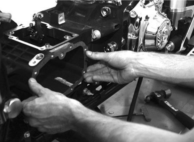 Step 4: Installing The Shifter Pawel And Snap Ring | FIGURE 5 |
5. Apply some WD-40 or equivalent lubricant tothe main drive gear seal and to the mainshaft (on the portion adjacent to the splines). Install the gearset by sliding the mainshaft through the main drive gear and slowly pushing the gearset assembly until the case dowel pins contact the dowel holes in the side door. | 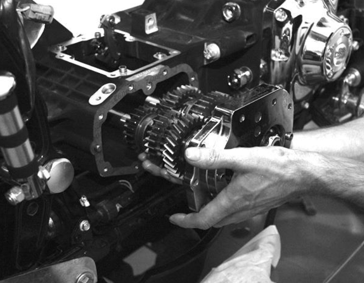 Step 5: INSTALLING THE GEARSET | FIGURE 6 |
Be sure that the threads in the end of the mainshaft do not contact the seal in the main drive gear. If the shaft tears the seal, leakage will occur. A rubber hammer is helpful to tap the bearing door gently. WARNING: IMPACTING THE ENDS OF THE TRANSMISSION SHAFTS WILL CAUSE THE DOOR BEARINGS TO FAIL.
6. Install the four 5/16-18 x 1-1/4 SHCS(socket head cap screws) along with the washers in the lower four holes in the bearing door. Use a small amount of Blue thread locker on the end of the threadsand torque the bolts to 13-16 ft. lbs.(156-192 in.lbs.) | 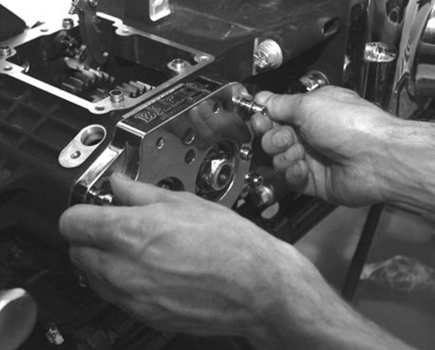 Step 6: STEP 6:INSTALLING THE FOUR SHCS | FIGURE 7 |
Install the two 1/4-20 x 1 1/14 with washers in the same manner above the dowel pin holes and torque them to 7-9 ft. lbs (84-108 in. lbs).
Shift Fork Installation
Figure 8 shows the proper placement of the shift forks. Fork number 4 is placed on the shift clutch between the 4th and 5th gears on the mainshaft. It will be necessary to engage the 4th gear on the mainshaft with the shift clutch. This will make installing the number 4 fork easier. | 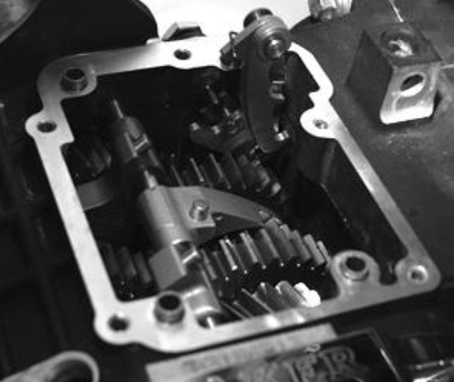 PROPER SHIFT FORK ALIGNMENT. | FIGURE 8 |
Function Check
The three forks should operate smoothly along the bearing grade fork rod once installed. If binding occurs, check for proper placement and/or obstructions inhibiting the ease of fork movement. At this time, apply a generous amount of WD-40 or transmission oil to the forks and fork rod.
Shift Drum/ Detent System
The shift drum and pillow block system of the BAKER DD6 transmission was designed with low friction and ease of operation in mind. Inside the shift drum is a ball bearing that reduces friction. | 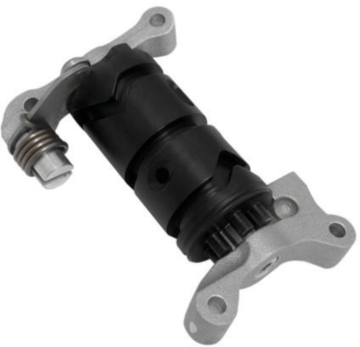 Shift Drum| FIGURE 9 |
No shimming or setup is required with the shift drum and pillow block system. The right side pillow block has another provision known as “redundant neutral detent”. The “redundant neutral” feature of the drum aids in finding neutral with less effort.
Install the shift drum assembly as detailed in Figure 10 making sure that the fork pins are properly riding in the drum. Install the provide 1/4-20 x 1/1/4 SHCS along with washers as you would with a stock drum. | 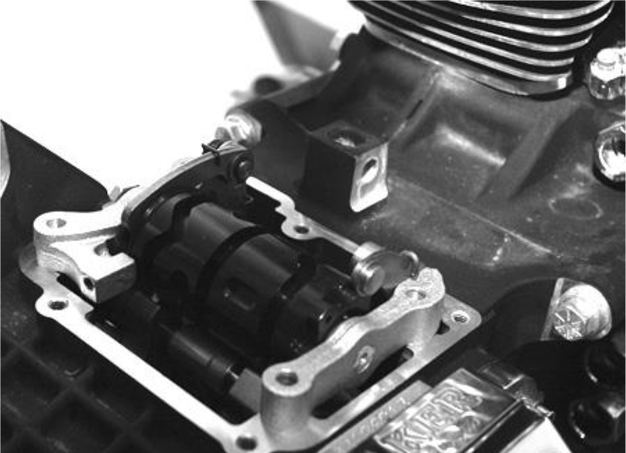 FIGURE 10 |
Put a small amount of Blue threadlocker on the ends of the bolts and torque them down in a circular patter 7-9 ft. lbs. (84-108 in. lbs.).
Shifter Pawl Adjustment
All models shifter pawl is adjusted in 3rd gear. All kit’s will include a replacement eccentric screw and jam nut for pawl adjustment. The eccentric screw must be timed to the shifter pawl so they move on the same axes. The directions will be described as looking at the bike from the left side. When you turn the eccentric screw clockwise the shifter arm should transverse to the rear of the bike. When you turn the screw counterclockwise the arm should move to the front of the bike. If this is incorrect the eccentric is off 180 degrees, turn the eccentric ½ turn clockwise. Now that the eccentric screw and shifter pawl are timed correctly, put the transmission in 3rd gear.
With the transmission in 3rd gear adjust the pawl to have equal free play (do not force against return springs) front to back on the dowel pins. Tighten jam nut, now double check shifter pawl adjustment, as seen in Figure 11. | 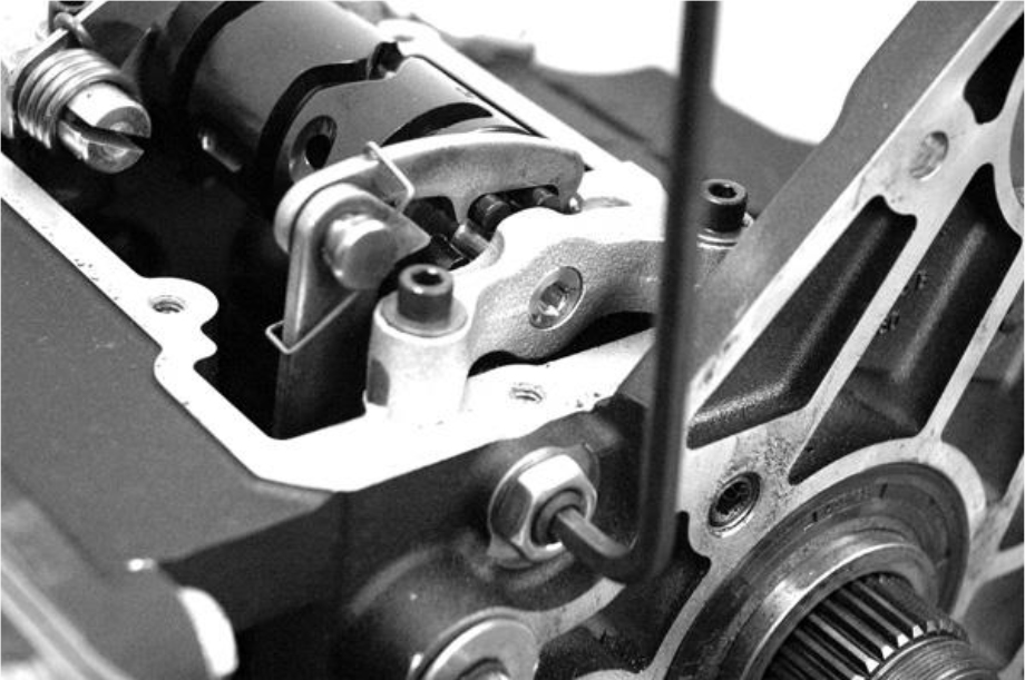 PROPER SHIFTER PAWL ADJUSTMENT IN 3RD GEAR |FIGURE 11 |
Reassemble the remaining components of the transmission as you would any stock 5-speed as detailed in the Factory Service Manual.
Neutral Switch
Depending on the year of the motorcycle, it may be necessary to replace the neutral switch. All ‘00 - ‘06 Softail models along with the ‘01 - ‘06 FLT and ‘05 FXD models , with a black body switch, require installation of the neutral switch, silver body, provided for proper neutral light function. | 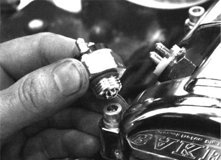 REPLACING THE NEUTRAL SWITCH |FIGURE 12 |
PRIMARY CHAIN AND SPROCKET INSTALLATION
Provided as part of the DD6 Builder’s Kit is a 28 tooth compensating sprocket, primary chain, and tensioner with hardware (with some kits), to be assembled as shown in Figure 13. | 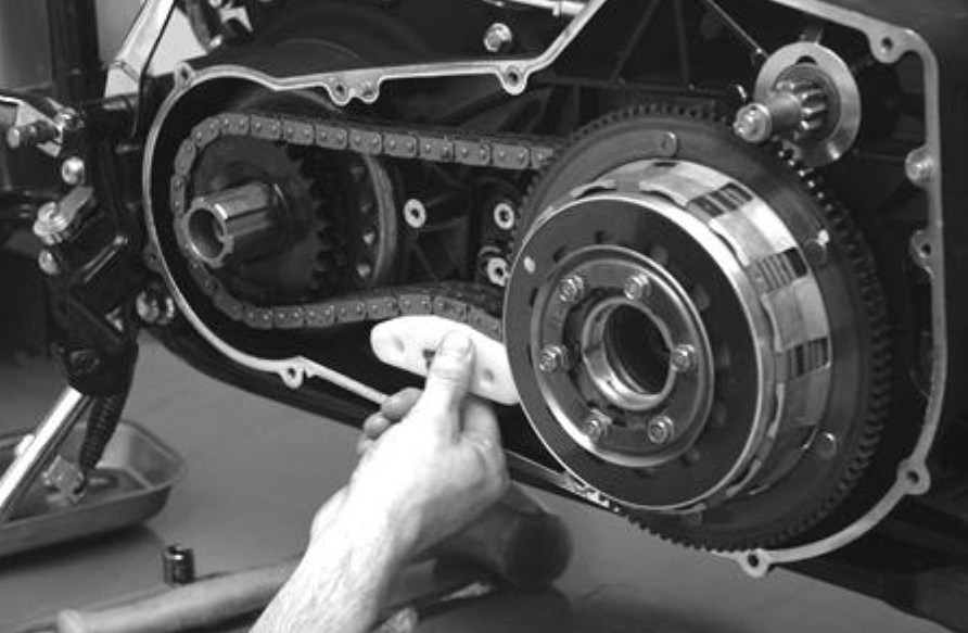 |FIGURE 13 |
Figure 14 displays the parts included in the kit, as follows:
1. P/N: DD6-177 Adjuster Retaining Nut | 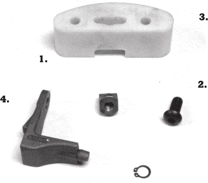 FIGURE 14 |
Some bikes are equipped with the late style chain tensioner, and only require a thicker shoe (P/N: DD6-178). Other bikes will require the late model Chain Tensioner (P/N: 39990-01) as well as using the altered bolt and nut that we include in the kit (See Figure 14 and Figure 17). | 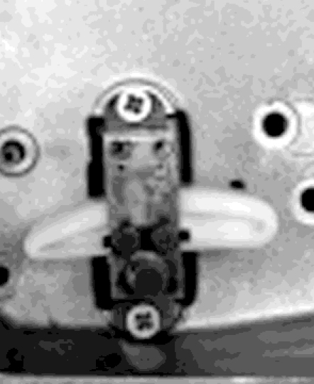 FIGURE 15 |
On Some models you will have to clearance the 2 pedastals on the inner primary that the chain inspection cover bolts to. In those application situations you will have to heli-coil the outerprimary cover for the two bolts that you clearanced. | 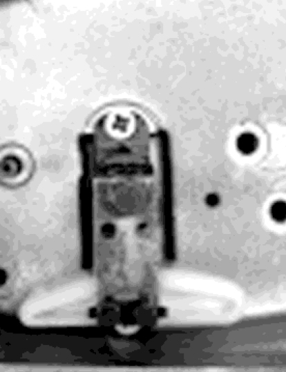 FIGURE 16 |
For most older applications you will be able to flip the entire tensioner (Figure 16) upside down (Figure 2) and that will accomplish the difference required. We do not recommend using “auto tensioners” from any manufacturer with our DD6 Builders Kit. | 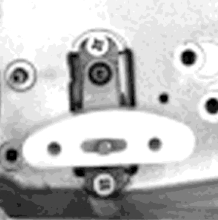 FIGURE 17 |
Speed Sensor Installation
Provided in the kit is a speed sensor spacer. Remove the speedometer sensor from the transmission case and place the spacer plate (paper gasket) under the stock sensor. | 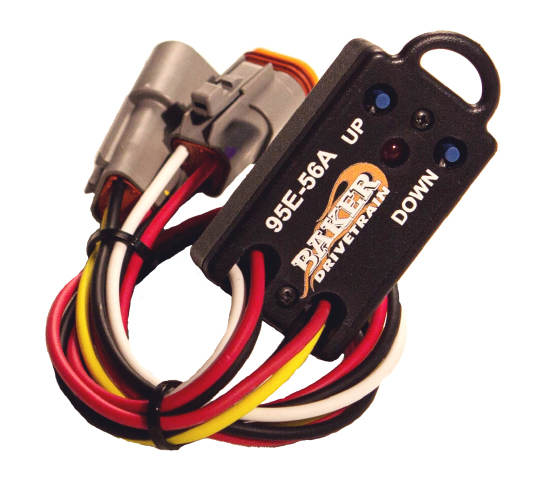 BAKER SPEED SENSOR SIGNAL CONVERSION BOX. PART NUMBER 95E-56. |
This is important to maintain proper spacing to the 5th gear on the mainshaft. The gasket is only .060 thick, so be careful not to over-torque it. You may require a speed sensor signal conversion box to correctly re-calibrate the speedo head. This unit and is available from BAKER DRIVETRAIN, part number 95E-56.
Fluid Fill
Fluid capacity is 20-24 fluid oz. of oil.
BAKER recommends using Spectro Heavy Duty 6
Speed Gear Lube, however any of the following oils
can be used: | 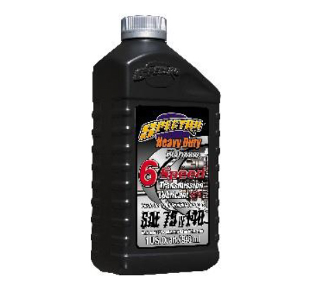 BAKER DRIVETRAIN RECOMMENDS USING SPECTRO HEAVY DUTY 6 SPEED GEAR LUBE. |


