Baker Drivetrain King Kong Clutch Installation
Features:
- 1 Piece steel clutch basket design
- 66 tooth ring gear configuration, 23% thicker than stock
- 20 massive 7" diameter single sided friction plates
- Red hard anodized carrier and pressure plate
- Hard anodized inner hub for wear resistance
- Positive pressure plate alignment accomplished with teflon coated perma glide bushings
- Coil spring design with 3 different springs included
Application And Required Hardware:
- 1990-2006 Softail/Dyna Applications (Except 2006 Dyna Motorycles) (94-06 Softails require James™ Gasket P/N: 60539-94 - thicker than stock)
- 1994 -2006 FLH Models. (James™ Gasket (P/N: 34901-94) is required - thicker than stock.
Skill Level:
As with most things in life there is no substitute for skill and experience. It is highly recommended by BAKER Drivetrain that when performing this task or any task related to the Drivetrain components on your motorcycle, that you refer to your Factory Service Manual for your specific model of bike.
Special Tools:
- 1 3/16” Socket (clutch nut removal)
- 1 1⁄2” Socket (compensating sprocket nut)
- Torque wrench
- 3/16” T-Handle allen
- Die grinder or cut-off wheel for 94-06 Big Twin (Except 06 Dyna Motorcycles)
- ATF (Dexron/Mercon) fluid
Included Parts
Parts Provided With The Baker King Kong Clutch
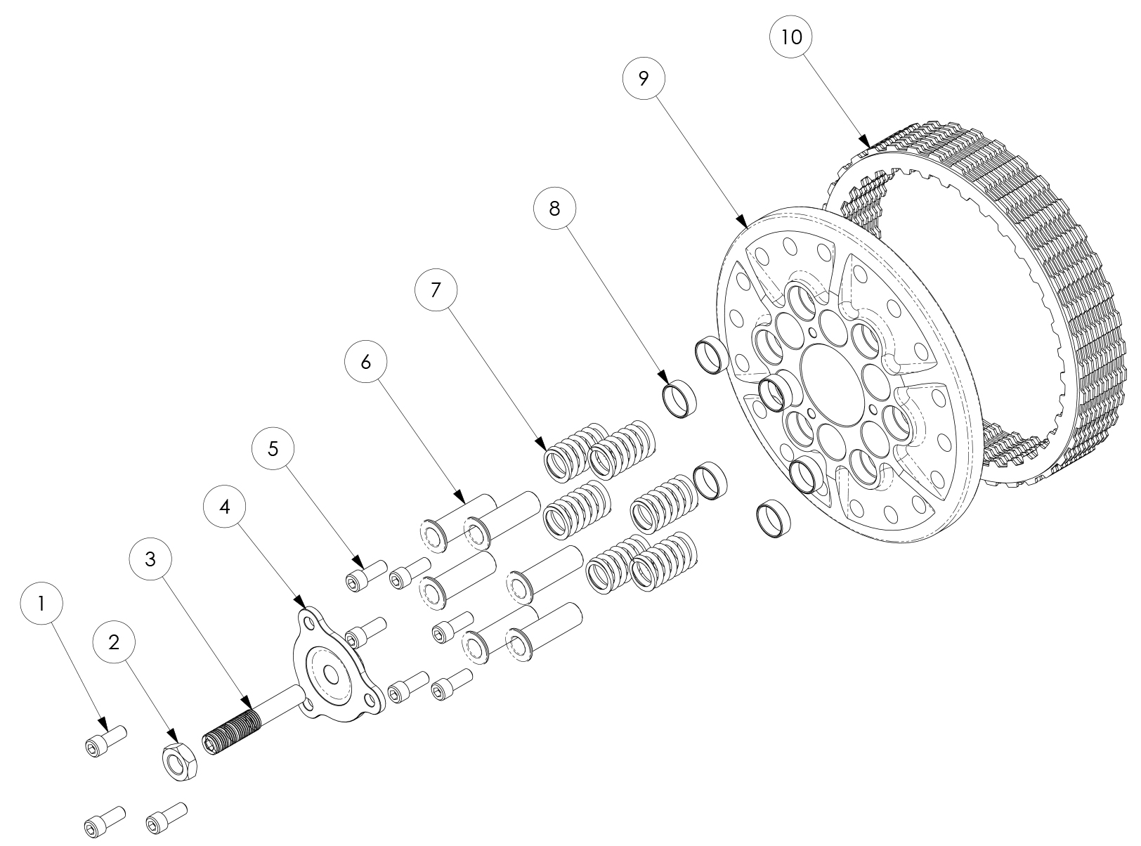
Figure 1.
The following parts are included as shown in Figure 1.
| P/n: | QtY: | Description: |
| 1 | 23202 | 3 | 1/4-20 X 5/8” sHcs |
| 2 | 36258 | 1 | 7/16-20 JaM nut- GraDe 8 |
| 3 | 9P235-56 | 1 | aDJuster screw |
| 4 | 20P107-KK | 1 | KeY Hole FIttInG |
| 5 | 004-242 | 6 | 1/4-28 X 5/8” sHcs |
| 6 | 20P111-KK | 6 | sPrInG cuP, PolIsHeD |
| 7 | lc-095J-05M | 6 | sPrInG, Yellow, 240 lbs. |
| 7 | lc-105J-05M | 6 | sPrInG, reD, 360 lbs. |
| 7 | lc-112J-05M | 6 | sPrInG, Blue, 480 lbs. |
| 8 | PaPZ1004P10 | 6 | PerMa GlIDe BusHInG |
| 9 | 20P105-KK | 1 | Pressure Plate |
| 10 | 156702-160 | 10 | Internal sPlIneD FrIctIon Plate |
| 10 | 156703-160 | 10 | eXternal sPlIneD FrIctIon Plate |
Parts ProvIDeD wItH tHe BaKer KInG KonG ClutcH contInueD...
Figure 2.
tHe FollowInG Parts are IncluDeD as sHown In FIGure 2.
| P/n: | QtY: | Description: |
| 11 | 002-359 | 6 | 1/4-20 X 1 3/4” sHcs |
| 12 | 20P101-KK | 1 | Inner HuB |
| 13 | 20P104-KK | 1 | FlanGe / BacKInG Plate |
| 14 | 23202 | 6 | 1/4-20 X 5/8” sHcs |
| 15 | 143rrrI | 1 | 1 7/16” Internal snaP rInG |
| 16 | 732121 | 1 | 1 1/2” leFt HanD tHreaDeD retaIner |
| 17 | 20P103-KK | 1 | FlanGeD HuB |
| 18 | 20P100-KK | 1 | BasKet, clutcH |
| 19 | 20P102-KK | 1 | carrIer, clutcH |
| 20 | 10Fs0KFc | 9 | 10-32 X 1/2” FsHcs |
| 21 | 3207 | 1 | BearInG, Ina DouBle row, carrIer |
| 22 | 1460-137PP | 1 | snaP rInG, eXternal, FlanGeD HuB |
| 23 | 35258 | 1 | snaP rInG, Internal 72MM, carrIer |
| 24 | D4a-35 | * | sProcKet, 35 tootH |
| 24 | D4a-36 | * | sProcKet, 36 tootH |
| 24 | D4a-37 | * | sProcKet, 37 tootH |
| 24 | D4a-38 | * | sProcKet, 38 tootH |
* = custoMers PreFerence
Preparation:
DIssasseMBlY:
- For Your saFetY, DIsconnect BotH BatterY Posts (FaIlure to DO so coulD result In Personal InJurY).
- Remove primary drain plug located at the bottom of your primary, drain fluid and dispose of at your local recycler.
- On some models it is necessary to remove foot pegs / floor boards in order to remove the outer primary.
- Remove the outer primary cover.
- Refer to your Factory Service Manual to remove your stock clutch assembly and related primary components using the proper safety precautions and tools.

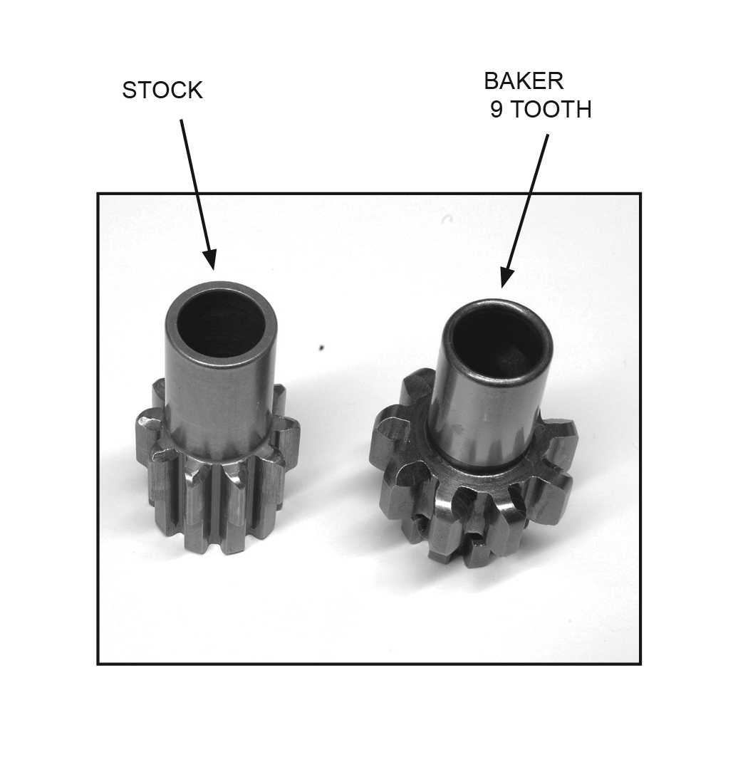
| 1994-2006 (eXcePt 2006 DYna MotorcYlces): reQuIres tHe use oF tHe BaKer 9 tootH starter PInIon (P/n sP1000) wHIcH converts Your 102 tootH clutcH conFIGuratIon Into a 66 tootH conFIGuratIon to worK wItH our clutcH BasKet. |
PInIon rePlacMent:
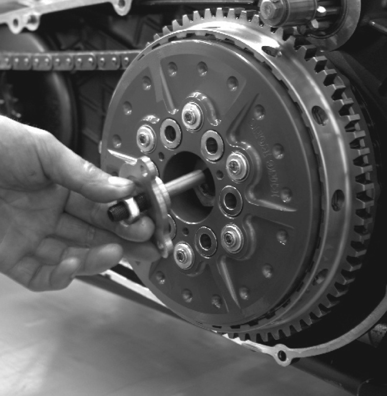
| With Clutch assembly and primary components out of the way, remove the factory 10 tooth starter pinion (H-D P/N 31342-94). Replace the factory pinion with BAKER’S 9 Tooth Starter Pinion (P/N SP1000) refer to the Factory Service Manual for proper torque specifications while reusing the Factory Hardware. (Fig 3) | Figure 3. |

| BaKer DrIvetraIn clutcH asseMBlIes all coMe PreasseMBleD anD reaDY For InstallatIon. FrIctIon Plates are PresoaKeD at our FacIlItY anD reaDY to run. |
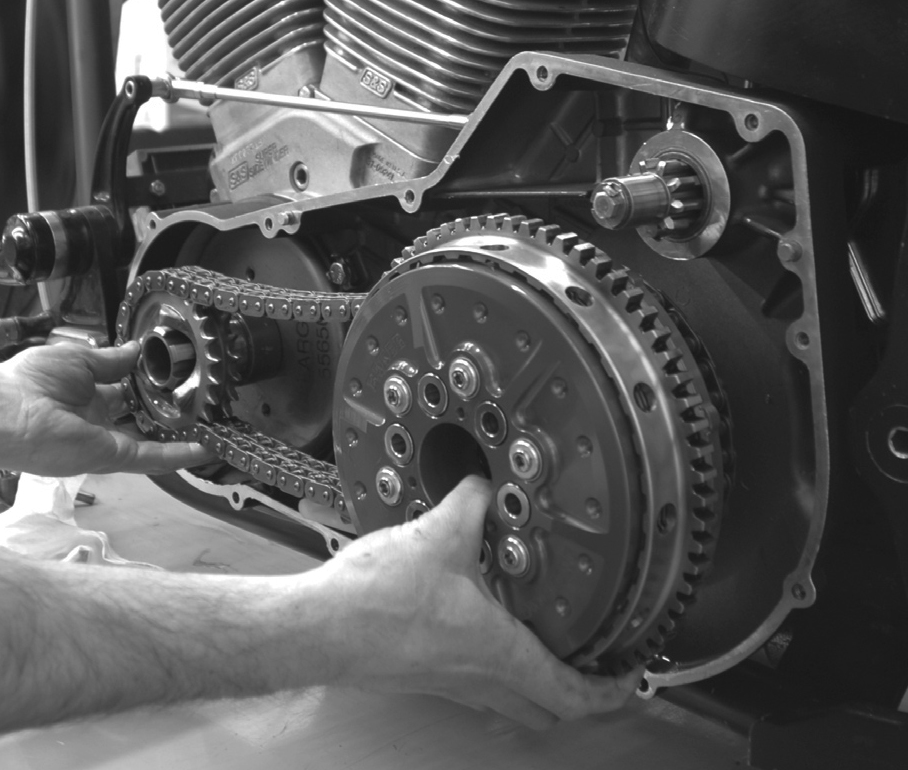
- Install your new clutch assembly, primary chain, and motor sprocket components following the Factory Service Manual. (figure 1.)
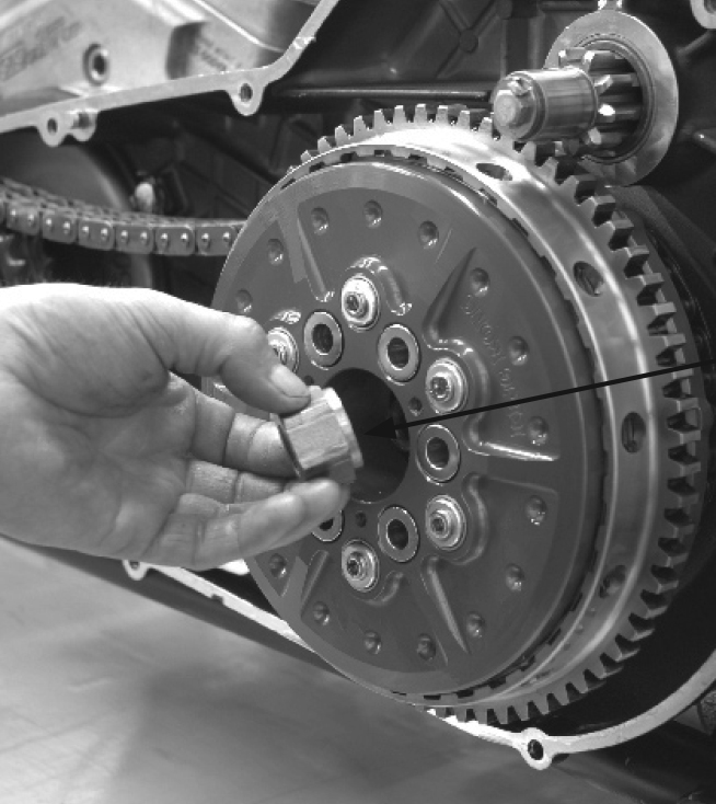
- Install the factory clutch nut (H-D P/N: 37496-90) with the machined relief facing toward the clutch using Red thread lock.
- Install compensating sprocket nut using “Red” Thread Lock.
- Torque clutch and compensating nut to Factory specifications found in your Factory Service Manual.
- Adjust primary chain following steps listed in your Factory Service Manual.
- Install clutch adjuster Key Hole Fitting with bolts provided in kit, using “blue” thread lock. Torque bolts to 110 in. lbs. (figure 3.))
- Adjust the clutch following steps listed in your Factory Service Manual.
|
Figure 1. |
Figure 2. |
Figure 3. |

| For 1994-2006 soFtaIl/DYna (eXcePt 2006 DYna MotorcYcles)
MoDIFIcatIon to tHe Inner PrIMarY Is nessessarY For ProPer FItMent. |
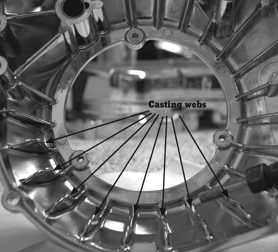
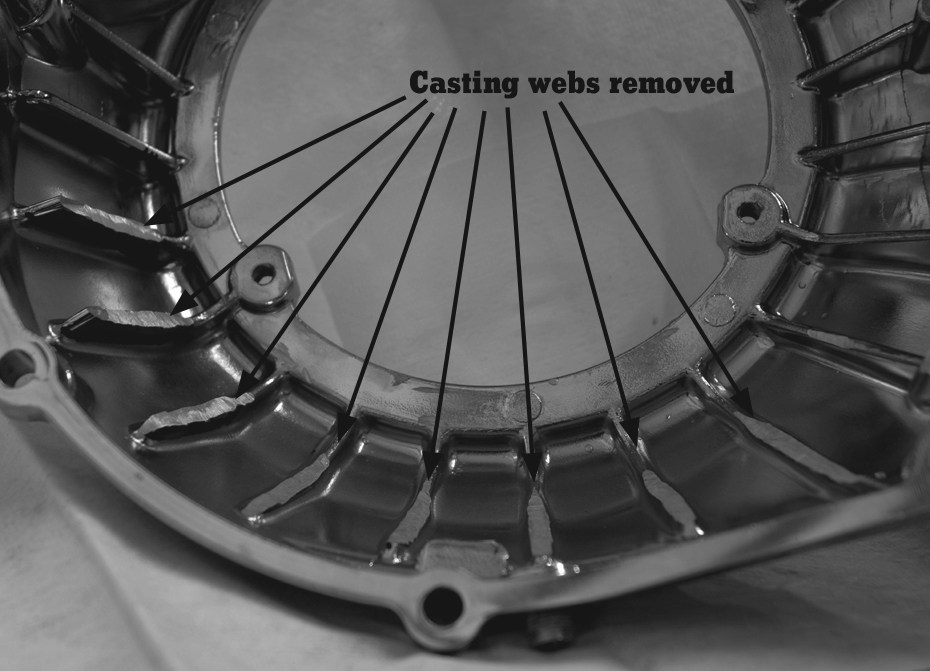
| 7a. Using a die grinder or cut off wheel remove the cast webbing from the inside of the inner primary. Remove webs entirely until smooth with the inside face. (Figures 4 and 5) A total of 8 ribs will be cut. |
Figure 4.Before removal of casting webs. |
Figure 5.after removal of 8 casting webs.. |

| 7B. cHecK Your outer PrIMarY FItMent to MaKe sure You Have ProPer clearance wItHout GasKet InstalleD. eXtra GrInDInG MIGHt Be reQuIreD. clutcH sHoulD sPIn FreelY, wItH Full clutcH actuatIon. FaIlure to cHecK MIGHt result In DaMaGe to tHe clutcH, Inner anD outer PrIMarY,
rInG Gear anD or Personal InJurY. |
- Install outer primary with new gasket following the Factory Service Manual. FLH models require JamesTM Gasket P/N: 34901-94. Softail/Dyna models 94-06 (except 06 Dyna), require JamesTM Gasket P/N: 60539-94.
- Add ATF (Automatic Transmission Fluid Dexron / Mercon) available at your local auto parts store referring to your Factory Service Manual for proper fluid level specifications.

| Due tHe KInG KonG ClutcH BeInG a HIGH PerForMance clutcH asseMBlY we recoMMenD onlY tHe use oF atF (autoMatIc transMIssIon FluID). atF Has FrIctIon MoDIFIers anD Better luBrIcatIon cHaracterIstIcs tHan FounD In orDInarY PrIMarY FluID. tHe use oF orDInarY PrIMarY FluID coulD cause tHe clutcH to slIP anD DraG, resultInG In clutcH FaIlure anD voIDInG Your warrantY. |
- Install derby cover (clutch inspection cover) with new gasket. Following your Factory Service Manual specifications.
- If floor boards or pegs were removed to install your clutch reinstall them as per Factory Service Manual.

| to ensure a lonG servIce lIFe For Your new BaKer KInG KonG ClutcH re-aDJust tHe clutcH Per Manual aFter tHe InItIal “BreaK In” PerIoD. tHIs can verY DePenDInG on Your rIDInG stYle; Between 500-3000 MIles. |
Your BAKER KING KONG CLUTCH is shipped with our red medium springs installed (rated at 60 lbs each). Depending on your riding style you can alter or tailor your spring load, following the steps listed here:

| note: wHen You cHanGe sPrInG Pressure Your lever eFFort wIll also cHanGe. |
InstallatIon oF coIl sPrInGs:
Refer to the exploded view #1 and Figure 6 as a guide.- Make sure the motorcycle is supported correctly on a lift or kickstand.
- Put the motorcycle in 1st gear (this will help when removing the coil springs).
- Remove the derby cover (clutch inspection cover).
- Loosen the clutch adjustment.
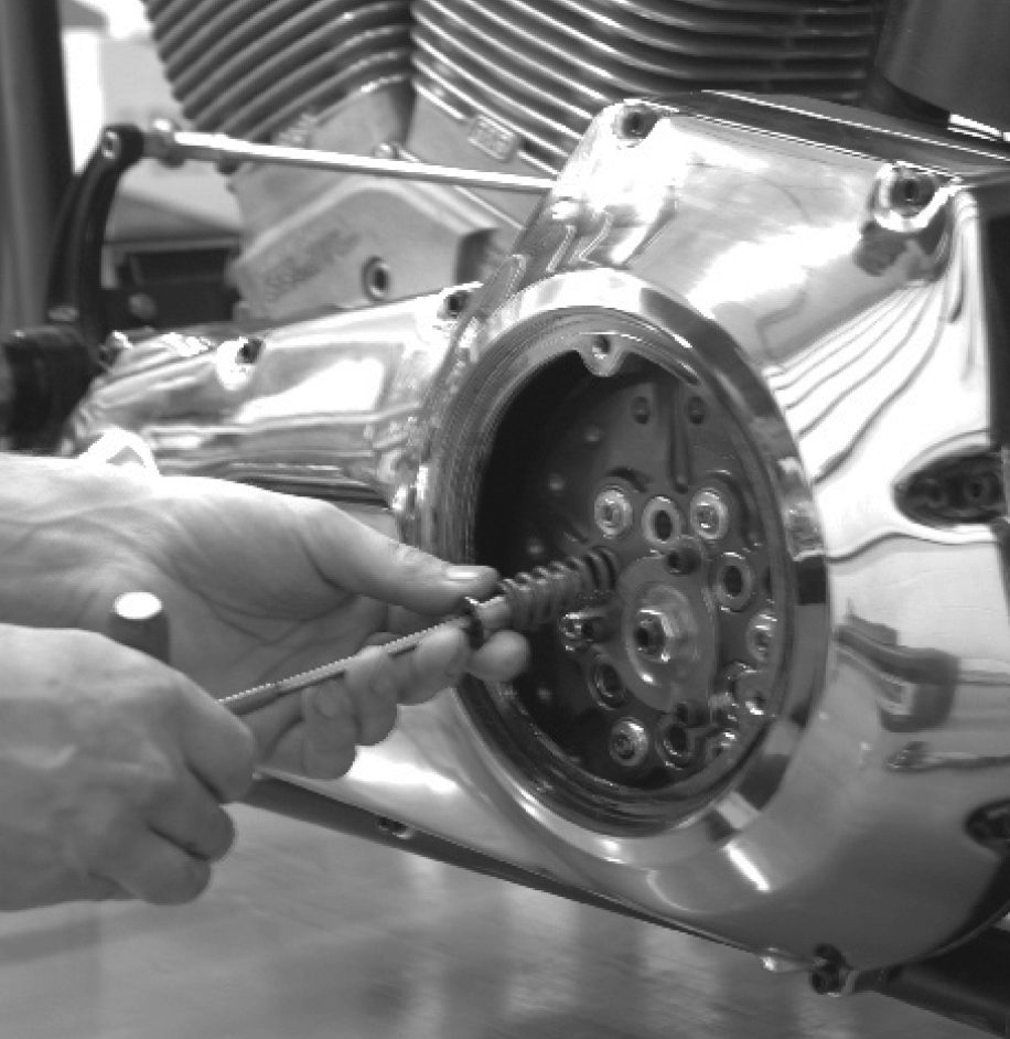
- Using a 3/16” T-handle allen remove 4 of the 6 springs. (leaving 2 springs, 180 degrees apart). This is to hold the clutch pressure plate and clutch pack together.
- Reference the spring chart on page 9; if mixing the springs mix equally, every other one; install 4 of the desired springs (some pressure is required on the T-handle when installing the retaining bolts) using “blue” thread lock. Torque to 110 in. lbs. in a star shaped pattern.
- Remove the 2 springs that you left in (Step 5). Replace them with the remainder of the desired springs using “blue” thread lock torque to 110 in. lbs.
- Readjust the clutch following your Factory Service Manual.
- Install derby cover (clutch inspection cover) per Factory Service Manual.
| Figure 6. |
King Kong Clutch Spring Chart
There are 3 different springs available for your clutch. We recommend the following:
- Yellow (P/N LC-095J-05M) for stock applications
- Red (P/N LC-105J-05M) for modified motors up to 150 h.p.
- Blue (P/N LC-112J-05M) recommended for race
applications only. Motors over 150 h.p.
note: a motorcycle being shifted with the throttle wide open will require more spring pressure than shifting with the throttle rolled closed.
| Color | # of springs | Yellow | Yellow / Red | Red spring | Red / Blue | Blue |
| lbs. rating | 6 | 240 lbs | | 360 lbs | | 480 lbs |
| Mix rating | 3 of each | | 300 lbs | | 420 lbs | |
BaKer Drivetrain does not recommend altering the spring pressures other than specified above. Doing so could result in clutch damage, failure, void of warranty, loss of control and or personal injury.


